
Guest Blog — Charles Guan Gearing Up (and Down) with Markforged
This guest blog is written by Charles Guan, a MIT Mechanical Engineering graduate and former MIT machine shop & design instructor. He’s also the builder of the robot Overhaul on ABC’s BattleBots, airing this summer Thursdays 8pm Eastern/7pm Central. He works as a engineering consultant in robotics and transportation, and is sponsored by Markforged to compete in BattleBots. Check out his website and Equals Zero Robotics.
Some Combat Robot Background
In the robot fighting world, there’s a couple of basic designs you tend to see all the time – there’s your wedges, flippers, hammers, spinning rotors, and so on. Like the Legendary Pokemon, some designs are “holy grails”, rarely seen and even more rarely well-executed in the arena. The “flywheel flipper” is one of those. Typically, your high-speed flipping arms, which are the ones seen throwing opponents several feet in the air, are pneumatic. But pneumatics, while power-dense, is not energy dense, and even the best flippers get less than a dozen good shots in before they literally run out of gas. The electric flywheel flipper combines the high energy density of batteries with the high power availability of a flywheel’s kinetic energy.
Channeling this energy into a quickly releasable, yet controllable form, has been elusive. The design challenges include a reliable engagement mechanism, consistent timing, gradual acceleration, and a robust linkage to the business end. Mess up any one of these and you might as well have built a a kinetic energy grenade.
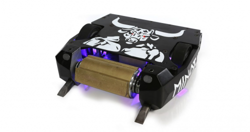
Only a few examples in all of robot fighting history have been made. On the small end, there’s Zac O’Donnell’s series of 3 to 30lb class robots, including his bot Magneato, and Dale Heatherington’s relatively successful designs. For the big bots, Warrior has been the benchmark.
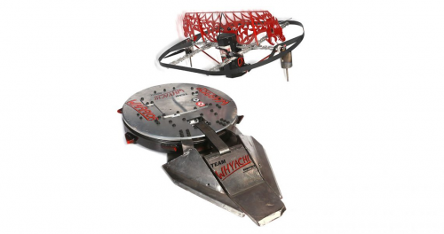
If you notice, each of these bots use a different design approach and final mechanism. This illustrates the level of exploration that the design has had in the community; robot designs tend to grow alike as a locally optimal solution is found by builders, so a weapon design with several means to the end is one which is yet untamed.
For a few years now, I’d been looking for a compact, coaxial solution to the problem that can be mounted inline with a “pointy flywheel” – a spinning drum or disc with teeth – and connected to a mechanism on the other side of the robot. That makes a dual-weapon robot with a lot of strategic possibilities. So I figured I would take the off season between BattleBots tournaments to pursue this idea further in a small 3lb robot, keep my design skills sharp, and help bust out another solution for the community. Why a 3lb class robot? Because it’s an easy size with which you can print using a Mark Two!
Designing the 3D Printed Gear Mechanism
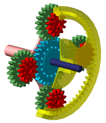
The requirements include packing a very high gear ratio (on the order of 20 or more to 1) into a coaxial volume and finding a way to engage that gear reduction only when necessary. I investigated planetary gear systems known as compound epicyclic gear trains, breaking out several reference books including the venerable “Mechanisms and Mechanical Devices Sourcebook” and scouring the Internet for design whitepapers. In short, this allows the creation of extremely high gear ratios in the same volume as a simple planetary gearbox by taking advantage of the relative speed of two ring gears of slightly different sizes.
After a short stint designing custom sliding dog clutches and friction bands, I realized I was just engineering my own automatic transmission. Complicated things usually don’t live long in battle, so I had to think of another way to use this gear reduction system. The solution lay in using the gearset as a torque splitting device. You might know this as Toyota’s “Hybrid Synergy Drive” or under any number of other trademarked infinitely-variable transmission names. This discovery came about, as many in history, by accident – I was spinning my CAD model and found that anchoring one ring gear made the other one still spin, and vice versa. I had forgotten that “relative velocity” meant one of those velocities can be zero.
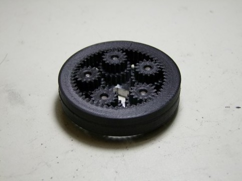
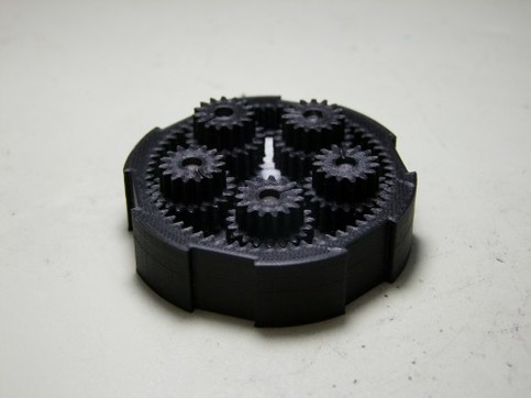
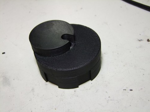
Excited, I quickly modeled up a toy ring gear and planet gear set, and printed it using Onyx on a Mark Two. Onyx is the only material I trusted would be strong and rigid enough. I was limited in what gear tooth sizes I could use due to the small size of the robot; regular nylon teeth would have been far too flexible. So I wanted to use the toy model to also be a tolerance gauge for the final product in case I had to make minor dimensional changes. The model confirmed my hypothesis that I just needed to suddenly stop one gear using any method – by brake, by clutch, or by simple virtue of a stick through the bicycle wheel spokes, and the other ring is forced to spin!
Geared Up For Robot Combat
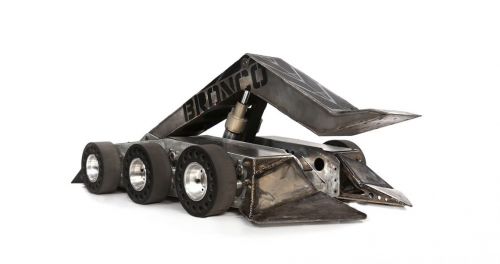
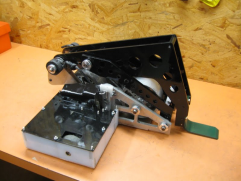
Work on the robot then started in earnest. I pulled out some of my ideation sketches from way back when and decided to just go for a “first pass” CAD model to get the concept down, and work on individual design needs from there. To keep a long story short, here’s a photo of the design as it stands now!
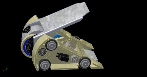
So what’s going on here? It has a triangular body that is invertible – there is no “upside-down” to speak of. The round silver object on the left is a 8 ounce aluminum rotor with socket head bolts as ‘teeth’, which is a common tactic in this small weight class for spinning weapons. The planetary mechanism is modeled in black (for Onyx), and a servo motor will push a sliding tooth into the notched ring gear on command, forcing it to stop rotating and the other ring gear to start. This ring gear has an offset cam lobe with a connecting rod to a “butterfly linkage” that forces the upper and lower metal wings apart as the cam rotates. The metal wings hinge at a common point, so one will react against the ground while the other heaves whatever is over it at the time upwards.
There’s details and geometric issues that still need to be resolved before this design is complete, but I’m now confident in the concept. It has its downsides – for instance, if the sliding tooth becomes stuck, the mechanism will be always on and the bot could lose mobility. If it dry fires with no weight on the wings, it will probably send itself up to the roof. But watching your design’s shortcomings make themselves very visible is part of the fun of the sport, so I look forward to seeing what will happen with this bot!
Here’s a demo of the system:
And here are some more pictures of the design:
Photos courtesy of Charles Guan.
All of the blogs and the information contained within those blogs are copyright by Markforged, Inc. and may not be copied, modified, or adopted in any way without our written permission. Our blogs may contain our service marks or trademarks, as well as of those our affiliates. Your use of our blogs does not constitute any right or license for you to use our service marks or trademarks without our prior permission. Markforged Information provided in our blogs should not be considered professional advice. We are under no obligation to update or revise blogs based on new information, subsequent events, or otherwise.
Never miss an article
Subscribe to get new Markforged content in your inbox