
Reinforcing 3D Printed Parts with Efficient Fiber Routing: Part 1
Editor’s Note: This is Part One of a series on efficient fiber routing techniques using the Markforged 3D printer. If you are unfamiliar with the printer and are interested in learning more, please contact us here. Once you are finished with this post, feel free to go more advanced with Part Two here!
Types of Fiber Fill
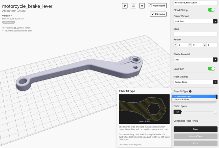
Our high strength 3D printers give you two different fiber fill strategies for reinforcing 3D printed parts: Isotropic Fiber or Concentric Fiber. You can apply these two options globally in the Part View page, or on a layer by layer basis in the Internal View page. The unique reinforced 3D printing process gives users a range of reinforcement tactics to choose from: each fill type has its own strengths and weaknesses, which we describe below. If you don’t have a Markforged printer and want to experiment with some of the tips listed below, get an Eiger trial to try out these tactics yourself.
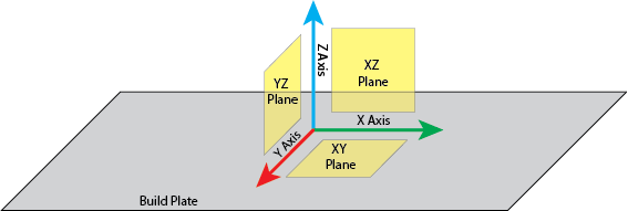
First, some standard naming conventions so that everyone is on the same page. I’ll be referring to strength in different axes and planes frequently, so use this key as a guide:
Concentric Fill Reinforcement
Concentric Fill simply traces a specific number of shells within the outside contours of your part, which helps reinforce from bending around the Z axis. By doing so, essentially reinforces the walls of the part, preventing the walls from deforming.
Concentric Fill tends to take longer because the movements of the print head are no longer linear and thus the print head must reduce speed to preserve accurate tool path tracking around curves. In this fill type, the print head follows the outer curvature of the part as it spirals inwards, so the more complex that curvature is, the longer it will take. When using concentric fill you can specify how many rings of fiber you want tracing the outline of your part, so you have good control over how much fiber you are using per layer.
Isotropic Fill Reinforcement
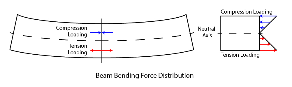
Our continuous fiber 3D printers can also print in an Isotropic Fiber fill pattern – this simulates the individual unidirectional layers of a traditional laminated composite. The pattern effectively creates a unidirectional ‘sheet’ of fiber on each layer you apply it to by routing all fibers parallel to each other in a single angular orientation, with 180 degree turns when the path reaches the edge of the part. Subsequent Isotropic Fiber layers in a fiber group are automatically rotated by Eiger at 45 degree angles to the orientation of the fiber in the preceding layer, although custom orientation patterns are certainly possible, which we will go into in Part Two of this post. The Isotropic Fiber fill pattern helps resist bending in the XY plane because any bending forces applied in that plane will generate a tensile load on at least some of the fibers, which are strongest in tension. Isotropic Fiber can also be used to set up sandwich panels to increase torsional strength on that plane, which I describe later on.
One thing you may notice is that isotropic fiber by default puts 2 concentric rings of fiber around the outside of the part. This ensures a smoothly reinforced external surface because the outermost fibers are always continuous and parallel to the edge of the part. While isotropic fiber is great for reinforcing the entire plane of each part, it is fiber- and time-expensive and it is not always necessary to create strong parts.
Basic Fiber Routing Techniques
With these two fiber routing options in your toolbox, there are now many different reinforcement options that utilize and combine both options. These techniques can help you save money, materials, and print time by allowing you to reinforce only when and where you need it.
Single Sandwich Panel
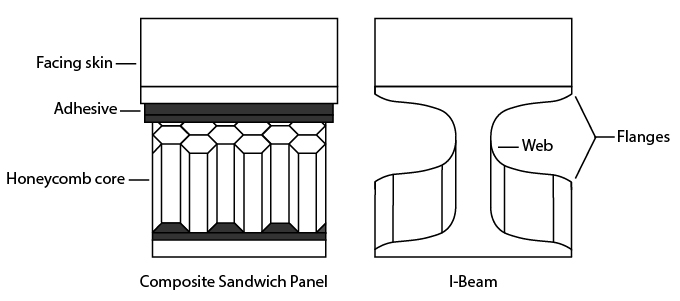
A sandwich panel is a common composite layup technique to reinforce for torsion around the surface that the composite sheet creates. As described in this blog post, a sandwich panel is the composite equivalent of an I-beam, with a stiff, strong material making up the top and bottom of a part – the top and bottom planes undergo the most bending stress so they are often the most reinforced. If you know that your part is going to encounter torsion on the XY plane, a sandwich panel will improve the part’s torsional strength.
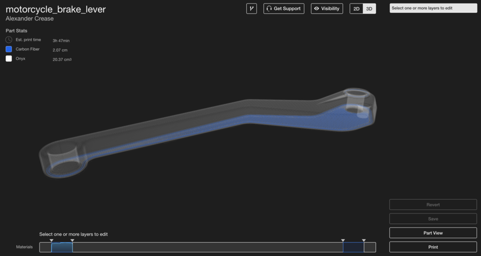
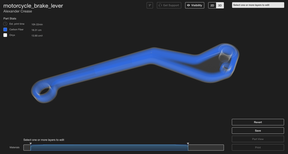
Our software will automatically generate a sandwich panel once “Use Fiber” is selected. However, this should only be implemented if your part is symmetrical, as it will lay fiber in the top and bottom few layers of your part. In the image below, note how the top of the brake lever is actually a small extrusion, so fiber needs to be manually added it makes more sense to put fiber beneath the largest surface near the top of the part. In general, it is best to have a sandwich panel consisting of layers with very similar cross sectional areas.
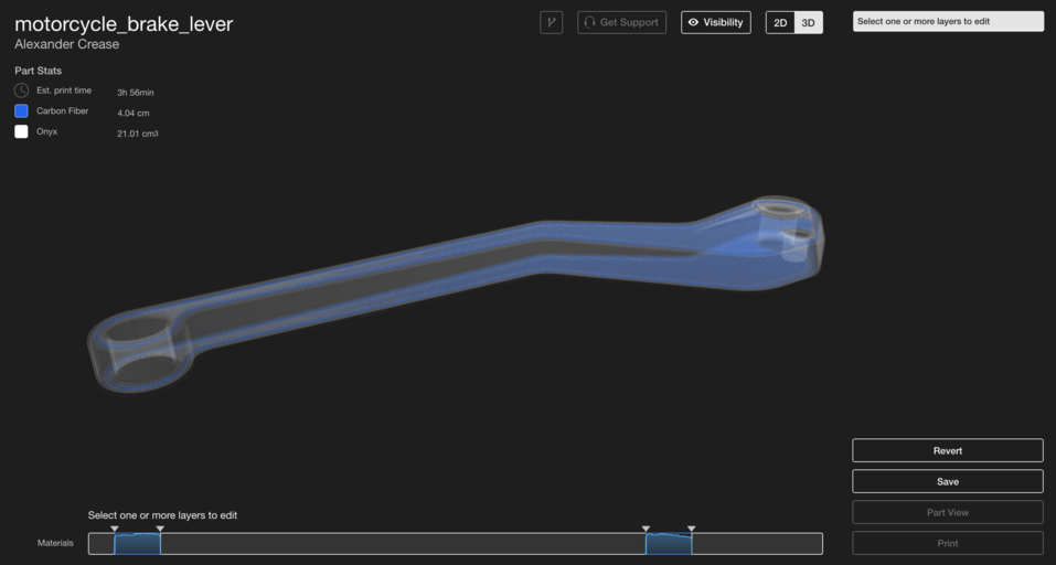
In order for the sandwich to be even, be sure that there are an equal number of isotropic layers on the top and bottom surfaces you wish to reinforce. Sandwich panels need to be even, or else If not, your part will be stronger in bending in one direction and not in another, and may break or warp more readily in one direction. The more layers of fiber you have on either side and the further apart the sandwich is, the stronger your part will be. Isotropic fiber layers in the center of your part will have less of an effect on the bending strength of the part, so entirely packing a part with fiber to provide strength in bending isn’t necessary.
Fiber Perimeter
While sandwich paneling increases strength around the XY plane, creating a Fiber Perimeter will make your part stronger around the Z axis. By using the Concentric Fill option on every layer of your part, you can increase strength in bending around the Z axis. As I mentioned earlier, Concentric Fill reinforces the walls of your part, so creating a fiber perimeter within your part makes those walls much harder to bend. This is why many engineering materials take the form of C channels or tubes instead of blocks: to reduce weight but conserve strength.
To set up a Fiber Perimeter in your part, use concentric fill on the layers you wish to reinforce. By increasing the number of concentric rings or increasing the layers in which concentric rings are used, you can increase the strength of the part around the Z axis. The brake lever below will experience bending stress about the Z axis, so I have reinforced every layer with 3 rings of concentric fiber to maximize stiffness. Just like with sandwich paneling, the middle of the part encounters the least bending stress, so the part doesn’t need to be reinforced with rings all the way to the center.
Shelling
What if your parts need to have increased bending stiffness on each axis, or you don’t quite know how they are going to be loaded? You can reinforce parts from flexing on every axis by combining these two techniques. With a sandwich panel on the top and bottom and shells of fiber in-between, the flexural strength of your part is improved on every axis. This motor bracket for a heavy-duty robotics application needs to be strong, but may experience loads from any direction, so something like this needs to be heavily reinforced from all sides.
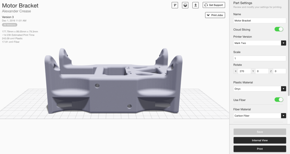
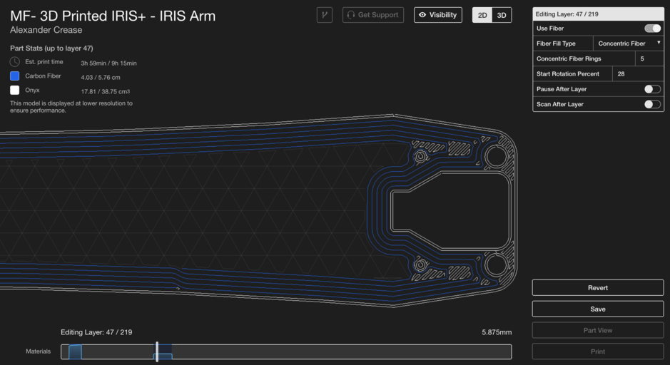
I want this to be a very robust part, so I selected 20 layers of isotropic fiber sandwich paneling (10 per side). However, because of the bolt-hole extrusions on the top of the part, I need to adjust the upper fiber “panel” and place it beneath the top face of the part.
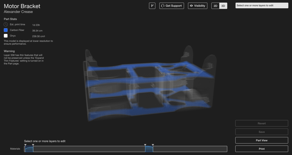
The bar at the bottom allows you to control different sections of fiber and displays how much fiber each layer has, normalized to the largest amount of fiber. In the image above, you can see two sections of fiber reinforcement for a simple isotropic sandwich panel. Now I can select the center region between the two “panels”, create a group, and set the fiber routing to Concentric Fiber Fill with 2 concentric fiber rings.
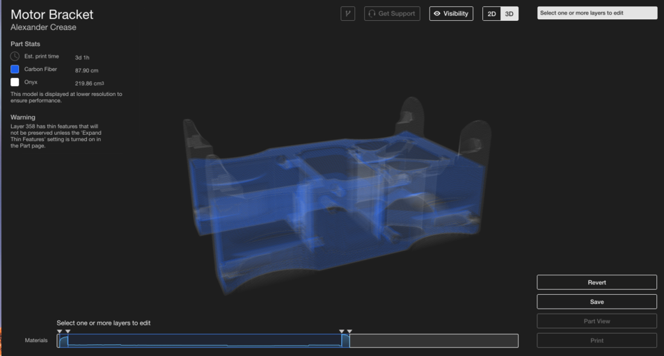
This part is now efficiently reinforced in bending through use of both Isotropic and Concentric Fiber Fill. By understanding how each type of fiber fill configuration reinforces a part, you can develop simple tricks like this to improve part performance and print time without wasting unnecessary fiber. Look out for part two of this post, where we’ll cover more advanced techniques for optimizing part strength with fiber orientation!
Interested in learning more? Request an Eiger Trial to experiment with our software and fiber reinforcement options. Also check out Part Two of this post, with more advanced fiber routing techniques!
All of the blogs and the information contained within those blogs are copyright by Markforged, Inc. and may not be copied, modified, or adopted in any way without our written permission. Our blogs may contain our service marks or trademarks, as well as of those our affiliates. Your use of our blogs does not constitute any right or license for you to use our service marks or trademarks without our prior permission. Markforged Information provided in our blogs should not be considered professional advice. We are under no obligation to update or revise blogs based on new information, subsequent events, or otherwise.
Never miss an article
Subscribe to get new Markforged content in your inbox