
MMF #5: A Guide to Embedding Components in 3D Printed Parts
Markforged Mechanical Features [MMF] is a series of blog posts detailing best practices for designing common traditional engineering parts and mechanical features for composite reinforced 3D printing with Markforged printers.
Last week, we explored overprinting nuts as a method for strong connections within your industrial strength 3D printed parts. In this post, we’ll take it a step further: by using overprinting to design multi-material parts when different materials are needed in different components of a part. As a brief overview, the process for overprinting is fairly simple. You start a print, pause it midway, embed components into the 3D print job, and then resume the print, allowing it to 3D print over the components you have embedded.
This could be used to develop a more integrated product, with electronic components embedded in 3D printed parts, it could be used when two materials are needed in the same component for desired material properties, or, in the case I will be explaining below, can be used to prototype parts to be made with more expensive manufacturing processes before committing to large batch quantities. For this post, I’ve designed a pair of 3D printed pliers with customizable jaws and an ergonomic grip.
For this pair of pliers, I wanted a stiff body, but comfortable grips. The Onyx is a bit rough for grips but pretty stiff (especially with fiber reinforcement), so I used Onyx and fiberglass to 3D print the body of the pliers and jaws of the pliers and a comfortable, tough nylon 3D printed grip.

Designing for overprinting fundamentally branches from design for assembly: how can you make putting components together easy and fast? Because you are embedding components mid-print, and the printer needs a flat surface to print on and the print head must not intersect with the part being embedded, designing for overprinting thus comes down to designing a good cavity. So here’s a guide on modeling and 3D printing parts with embedded components.
Designing the Void:
When designing for overprinting, as I mentioned before, you will be embedding parts in a void. When you start your part design, you should think about which face the part will print from right from the beginning, as you’ll need to know this in order to properly embed a part. For this part, I want to embed the main body of one side of the pliers into the grips. All these parts happen to be 3D printed, but only the grips have to be for this case. If you are overprinting a part, you may need it to entirely fit within the printed piece, or like in the case of this set of pliers, you may just want to place a section of the part in, in which case you will need ribs or some other sort of feature to keep the part constrained, as shown below.

To create the void, you’ll need a good CAD model of both the part you will 3D print and the part you will embed, then creating the void is as simple as creating a boolean operation: subtract the part you will embed from the 3D printed part. If the part you are embedding has filleted or chamfered top edges, those features will need to be removed from the part you are 3D printing – a flat ceiling is necessary.

In CAD, you will also need to check for is features in the embedded part that will intersect the build plate or the extruder head. If a section of the part you are embedding extrudes up above the cavity, there is a chance the build plate will hit it. To account for this, you either should try to ensure that the part you are embedding has a flat top surface, or that the extrusion is far away enough that there is no chance the extruder head will hit it, taking into account all the movements of the extruder head, including zeroing and dislocation checking. On the Mark Two, the plastic nozzle is about 35 mm from the front of the print head, so anything features in your embedded part closer than that may get hit by the print head In these cases, you must orient your part such that the embedded part is jutting out toward the front of the printer. If it juts out of the side or back, the print head has a higher chance of knocking into it because of the way the print head zeros and runs dislocation checks. For example, in the pliers I designed, the jaws are raised higher than the flat the grips will be printed around. The jaws were spaced to clear the extruder head, at just over 35 mm.

A really important step to remember when designing your 3D printed part is accounting for tolerance. After you’ve performed the boolean operation, you’ll need to offset each face by about .08 mm on every face to ensure that you will achieve a surface flush with the layer this part will be paused on. This also applies to the walls of the cavity – if you can’t fit your part inside the cavity because the cavity is just slightly too small, then you won’t be able to fix it unless you print a new one! Better be safe than sorry and design the cavity a bit oversize.

If your top surface is an odd geometry, you’ll need to design a secondary insert to add to the cavity to ensure a secure fit that forms to the top surface of the embedded part. This process is explained in the latter half of my embedded nuts blog post from last week, and the exact same process can be implemented for other components. If you would rather not do this, one way to get around this involves angling the ceiling of the cavity above the inserted part, but then that means the component, depending on it’s geometry, may be loose within the 3D printed part.

Usually, when designing for overprinting, I try to avoid the use of support material. However, in some cases it it necessary to the design, and that’s not a problem: support material can be easily removed from the cavity before placing in the embedded component.
Adding pauses in Eiger:
In Eiger’s internal view menu, you can easily add a pause after a selected layer, making it easy to embed parts into your 3D printed components. Find the layer just before the roof of the cavity starts to print, and click “Pause After Layer” At that layer, you can note the time it will take to get to the pause and use that to determine when to check in on your print job.

Remember, if your parts do not require support material, it is a good idea to turn supports off. If they do, however, that’s fine! You’ll be able to remove them, as I’ll explain later.

When you orient your part on the build plate, keep in mind the accessibility of the part. You’ll want to be able to quickly pop the part in and resume the print, so orienting your part so that you can easily get to it. For this part, I placed it all the way up by the front so I could easily snap in the body of the pliers.

Adding the Part:
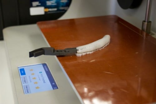
When it comes time to add the part to the print, timing and speed are key. As Markforged printers are FFF (Fused Filament Fabrication) machines, the plastic is heated, extruded, and cooled. When it cools, it shrinks slightly, which, if the print is paused for long enough, can cause much weaker layer adhesion on that plane. When placing a part into a print job, you want to do it as quickly as possible to reduce this risk. Using Eiger, you can estimate about when your printer will pause, so you can show up on time and be prepared for when your printer pauses.As I explained earlier, support material may be necessary due to other features in your design. For example, this grip requires supports because it has a complex bottom surface. In my case the void that I designed will fill with supports, but it’s not a problem – if this happens you can just pull them out before inserting the part.
Now it’s time to place the part into the print. This is why tolerances are so important. You need to make sure that the embedded component is perfectly flush or slightly below the layer that the print is paused at. If it is slightly raised, your print head will jam against the embedded component and mess up the entire print, or the filament will jam when trying to print over the component.
When a print pauses on the Markforged 3D printer, the print head moves out of the way, allowing you to easily remove the build plate from the printer and add your part. The kinematically coupled build plate ensures the print bed will snap right back in place when you want to continue.
If you are adding a component that is not a Markforged 3D printed part, then you will need to add a layer of glue to the top surface of the part. This glue is normally put on the build plate at the beginning of a print to help with build plate adhesion, and in this context we are using it for the exact same reasons – the nylon will stick better to the top surface of the part.
And after printing two of these and snapping in a small pin at the joint, I now have a pair of 3D printed pliers with customizable, swappable jaws and ergonomic grips!

If you want to make these yourself, here are the files:
Pliers and pin MFP (requires Onyx and fiberglass)
Custom JAW MFP (requires Nylon)
Other Applications:
The applications of overprinting range far and wide because it allows you to create fully integrated assemblies that could not have been created any other way. While this example represents embedding a section of a component to create an ergonomic grip, you can also embed whole components and the same rules apply. For example, you may want to prototype a part that will eventually be overmolded, or you may want to create a part with embedded electronics for an integrated electromechanical system. You may want to embed hidden nuts or bearings into a 3D printed part, or create a multimaterial build with a single plastic extruder 3D printer. If you have tried out overprinting and embedding components in 3D printed parts, please share with us on Twitter, Instagram, or Facebook!
All of the blogs and the information contained within those blogs are copyright by Markforged, Inc. and may not be copied, modified, or adopted in any way without our written permission. Our blogs may contain our service marks or trademarks, as well as of those our affiliates. Your use of our blogs does not constitute any right or license for you to use our service marks or trademarks without our prior permission. Markforged Information provided in our blogs should not be considered professional advice. We are under no obligation to update or revise blogs based on new information, subsequent events, or otherwise.
Never miss an article
Subscribe to get new Markforged content in your inbox