
Using Co-Part Assemblies and Continuous Fibers to Print Stronger Parts
By Peter Kelly, Research & Development Engineer
What if we told you that, in some cases, you can actually make a part stronger by printing it in multiple, separate pieces?
A few of my Markforged colleagues and I recently published a research paper in the Rapid Prototyping Journal, where we tested how additively manufactured co-part assemblies perform in tandem with our Continuous Fiber Reinforcement (CFR) process.
On their own, CFR and co-part assemblies lead to substantial strength improvements compared to equivalent parts. Together, they make parts even stronger — and in some cases are able to hold up to 6.4x the ultimate load of an equivalent Onyx part without CFR or a strategic co-part assembly.
Interested in learning how to maximize part strength with these techniques? This might not always be necessary — but if you have an edge case or need additional strength for a heavy load, this is for you.
I’ll explain the CFR process, why co-part assemblies are used to improve Z-strength, then walk you through a real world example of how to properly design, print, put together, and test a co-part assembly.
Printers and materials matter!
When it comes to the strength of parts, choosing the right 3D printers and materials makes all the difference. While many 3D printers can print common plastics such as PLA, ABS, and Nylon, the resulting parts are not suitable for many industrial uses that demand qualities such as strength, stiffness, heat and chemical resistance, plus durability.
While a number of 3D printers can print in stronger carbon fiber, Markforged 3D printers in particular can achieve even greater strength improvements. Markforged composite printers combine a base material discontinuously reinforced with carbon fiber (Onyx) with reinforcing continuous fibers laid through the part.
Continuous Fiber Reinforcement (CFR)
Continuous Fiber Reinforcement (CFR) is a proprietary process that allows Markforged printers to produce impressively strong composite parts. Reinforcing fiber materials include Carbon Fiber, Fiberglass, HSHT (High-Strength High-Temperature) Fiberglass, and Kevlar®.
How strong is CFR?
Adding proprietary CFR allows a composite part to hold up to 2.5x the ultimate load of an equivalent Onyx part without CFR. Onyx with CFR has a yield strength up to 800 MPa in the printed plane — nearly a 20x improvement from Nylon.
Combining CFR with a co-part strength design optimization allows parts to hold up to 6.4x the ultimate load of an equivalent Onyx part without CFR.
Markforged Eiger software lets you customize placement of continuous fibers within your part. There are basic and advanced strategies for reinforcing parts with fiber that you can learn more about here.
00:00
02:39
Why co-part assembly?
A huge advantage of 3D printing is the ability to design and print your part as a single unit. So, why would you want to go through the trouble of splitting your part into separate components, printing in multiple jobs, and assembling into the final part?
The answer is anisotropy. With fused filament fabrication printing, or FFF for short, parts are fabricated layer by layer. This means the X (left to right) and Y axes (front and back) will inherently have more strength than the Z axis (up and down).
This is primarily due to the bonds of thermoplastic materials within layers being stronger than the bonds between each different layer. While the orientation of a part can help mitigate some of the effects of anisotropy, a single part often has distinct features that demand a conflicting orientation to print properly.
So, for any part that falls into this scenario, we can break it into two or more parts and print them separately in their optimal orientations to minimize anisotropy — ultimately ending up with a stronger, more durable part.
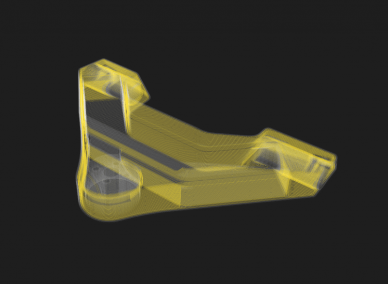
Co-part assembly example: mounting plate
This is a mounting plate designed to secure a tent pole to the ground. The plate is secured to the ground through four holes, while the tent pole is secured to this boss through this hole. This is a common case where the direction of the load is perpendicular to the plane that the part is mounted to.
If we printed this as a single part horizontally, the bottom plate would be strong — however, the part would fail in the plane with the lowest cross-sectional area when enough load is applied.

While we could turn it on its side to print the part vertically and give more strength to the center boss, this would make the plate weaker by bending one of the axes parallel to the plane of the printed layers. This would also add additional print time and material usage from supports.
By splitting the mounting plate into two distinct parts and printing them in their ideal orientations, we give them the ability to withstand higher loads when assembled together.
Tips for CAD modification
Here we have our mounting plate open in Solidworks. We don’t want to modify the overall geometry — the only modification we want to make is splitting the plate into two distinct parts.
First, we’ll need to determine 1.) how we’re going to separate this part, and 2.) the best way to transfer load between the parts.
The step-by-step Solidworks walkthrough starts at 1:52 of the video below:
00:00
07:19
Generally speaking, the optimal orientation is one where the principal loads through critical features are carried parallel to the printed layers. This minimizes loading in the interlayer, or printed Z-direction, where strength is the lowest.
When designing co-parts, you also need to make a trade off between print time, support material usage, and some other factors. The best strategy that I’ve found is to arrange the co-parts such that applied load attempts to pull one part through the other.
Once the parts are separated, we’re ready to import the files into slicing software and kick off the print.
Printing and assembling co-parts
Once the parts are printed, we’ll want to separate the supports from the part and remove any debris. Once we finish with that, we’re ready to assemble. There's two ways you can assemble the parts together.
- You can use an arbor press, by press fitting the parts together
- Or, you could use adhesives to secure them together.

One thing to note with adhesives, you’re going to want to do some research on which adhesives work best for your materials. If you’re using a Markforged printer with Onyx, we recommend using:
Loctite 401
Scotch-Weld DP100
or Scotch-Weld DP420
For other common 3D printing materials, such as PLA, PETG, and ABS, good candidates include cyanoacrylate adhesives, epoxies, and silicone glues.
I like to use an arbor press because it’s the easiest way to assemble co-parts and I know that this part will only be loaded in one direction. If you expect your part may undergo load in different directions, adhesives may be the best option.

Testing the mounting plates
We tested three different parts, all printed on a Markforged X7 with Continuous Fiber Reinforcement (Carbon Fiber).
- Part #1 was printed as a single unit horizontally, in Onyx with Carbon Fiber.
- Part #2 was printed as a single unit vertically, in Onyx with Carbon Fiber.
- Part #3 was printed as two parts in their ideal orientations, with Onyx and Carbon Fiber.
As expected, co-parts reinforced with continuous carbon fiber performed much better than the single parts. The co-parts reached a maximum load of 5747 Newtons, or about 1292 pound-force. That’s an 87% improvement over the next best mounted plate printed as a single part with continuous carbon fiber.
Other techniques for improving Z-strength on prints
While co-part assemblies are effective for many cases, there are other techniques for improving Z-strength which might be preferable for other parts: such as adding pockets for bolts to run through parts, or adding pockets for machine keys.
The video below shows an example of improving Z-strength in a bending die:
00:00
13:45
How can our technology make a difference for your team?
Interested in learning how easy access to strong parts can lower costs and streamline your manufacturing operations?
Talk to one of our experts — our team of Application Engineers and industry experts can answer any questions you have, from details about our material properties to building an additive transformation roadmap for your business.
Learn
Blog
Reinforcing 3D Printed Parts with Efficient Fiber Routing: Part 1
In this post we cover the basic techniques to reinforcing 3D printed parts with a Markforged 3D printer. Learn about fiber fill types and how to optimize them.
Learn
Blog

Why use the Digital Forge? Breaking down our additive manufacturing platform
Learn more about the technologies in our additive manufacturing platform — and how it makes us different.
All of the blogs and the information contained within those blogs are copyright by Markforged, Inc. and may not be copied, modified, or adopted in any way without our written permission. Our blogs may contain our service marks or trademarks, as well as of those our affiliates. Your use of our blogs does not constitute any right or license for you to use our service marks or trademarks without our prior permission. Markforged Information provided in our blogs should not be considered professional advice. We are under no obligation to update or revise blogs based on new information, subsequent events, or otherwise.
Never miss an article
Subscribe to get new Markforged content in your inbox