
Designing for Printing Part 1: 3D Printed Unit Tests and Tolerances
Welcome to our new blog series, Designing for 3D Printing (DF3DP). DF3DP is a blog series devoted to 3D printing tips and tricks to follow when using any 3D printer that will guide you through reducing costs, print time, and material while also showing you how to get your parts the way you want them first try.
We’ve all been there: you print out a part that takes hours, only to find that it doesn’t quite fit the way you wanted it to, thus wasting precious print time and material on a bad part. 3D printing is a hands off manufacturing process, so once you send your CAD model to the printer there isn’t much you can change. Parts can take hours or even days, and if you have a deadline to meet, entirely reprinting the part with corrected tolerances is sometimes not a luxury you can afford, either from a time or monetary perspective. Because 3D printed parts made with FFF (fused filament fabrication) printing shrink due to thermal contraction, 3D printers often do not print exactly the dimensions you tell them to, so accounting for tolerance is necessary. In this post, I’ll guide you through how to ensure the 3D printing tolerances are correct before printing the entire part out only to find they are wrong.
This is where unit testing 3D printed parts comes in handy. A unit test is traditionally a software term, essentially testing that small snippets of code work independently before incorporating them into the full script. We’re going to do the same thing with 3D printing: print small, quick segments of what will later be integrated into a larger design to verify or test their functionality and fit before printing out an enormous part.

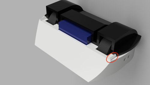
For example, the top of this prototype 3D printed antweight combat robot I’m designing slides onto the base via a set of dove-tail inspired grooves (one is circled below). Both parts combined take 4 days and 7 hours to print, so I want to make a 3D printed unit test to ensure the grooves are the correct size before I print everything.
Designing a Good Unit Test For 3D Printing
A well designed unit test should be quick and easy to both design and print (I usually aim for about a half an hour to an hour print job). I modeled a single miniature version of the groove pairs, and then made copies of it with different face offset distances, ranging from no offset to a -0.2 mm offset on all faces of the dovetail. This means that each male groove profile was thinner than the last.

I also added in numbering so I could remind myself which offset distance was which, as shown in the CAD screenshot below:

Testing The 3D Printed Unit Test
One thing to remember is to print your unit test in the orientation that the final part will be printed with, so that you can make the test as accurate as possible. The print only took 1 hour and 15 minutes, much better than printing the entire robot chassis and then finding my slide-on grooves were not toleranced well.

To test it, I just slide the female groove profile piece onto each male profile, starting from the largest face offset (-0.2 mm) and working my way to 0.0 mm offset.
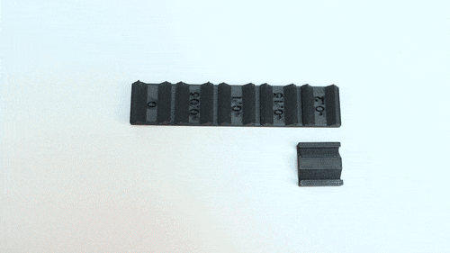
The -0.2 mm offset profile was very loose – I don’t want the top of the robot to just slide off. The -0.15 mm and -0.1 mm male profiles were decent but not as snug as I would like them. The -0.05 mm offset ended up being just right – it was snug enough that it couldn’t be knocked of easily, and I could slide it off with a bit of pressure. The final profile, 0.0 mm offset, was a bit too tight for my liking. Now, I can enter the -0.05 offset value into my final design, and I’m certain it will slide on the way I want it to. There are a few more features that will actually lock the top in place, but the grooves connecting the two pieces were the tolerances I was unsure of.

Other Uses of Unit Tests
Unit tests are really valuable for any sorts of tolerances, even if you just want to get a good sense for how your printer behaves under certain conditions. For example, to get a sense for hole tolerances on a given 3D printer, you may want to print something like this:

You can then measure the hole sizes and compare the measured value to the value dimensioned in your CAD model, thus giving you a good sense of the hole tolerance you’ll need to leave in each plane on parts you’ll be 3D printing. You can then use this test as a reference for future design work and it can assist in designing not just one, but many 3D printed parts.
Additionally, with our printer, you can take the unit testing process a step further: say you do need to print out this whole robot chassis, but you want to make sure all of the components fit inside before committing to using carbon fiber to strengthen the frame. You can make what is called a 3D printed fit prototype to test that all of your components fit inside your 3D printed parts (or the other way around) before introducing fiber into the print. This again reduces material waste and cuts down on costs so that you can test the final geometry and form of fiber-filled parts before committing to printing them.

The True Value of Unit Tests:
So lets say I printed this entire chassis and top, and I messed up the groove tolerance. Then I would need to print this entire thing twice, or I would have to spend a few hours hacking at a pretty weird small geometric feature, and nobody really wants to do that. Filing or sanding 3D printed parts to make them fit, especially when they involve small geometries, often leave scars, poor surface finish and they can accidentally break the feature or expose a 3D printed part’s internal structure. It’s pretty obvious that printing a large part twice isn’t as good as spending a bit more design time and then printing one small part and one large part, but here are the numbers for my robot in case you aren’t convinced about 3D printed unit tests just yet:

Unit tests are critical to large 3D printed parts if you want them to come out right on the first try. Post processing is a process that most people expect to just deal with when 3D printing, whether it is sanding surfaces, drilling out holes, or filing down mis-dimensioned joints. On a printer that is as reliable and precise as the Mark Two composite 3D printer, post processing doesn’t have to be a step that you need to take, and with unit tests you can ensure your parts will come out the way you want them to.
If you want to check out these tests for yourself, you can download them here.
Want to see more of what the Mark Two can do? Request a Demo today!
All of the blogs and the information contained within those blogs are copyright by Markforged, Inc. and may not be copied, modified, or adopted in any way without our written permission. Our blogs may contain our service marks or trademarks, as well as of those our affiliates. Your use of our blogs does not constitute any right or license for you to use our service marks or trademarks without our prior permission. Markforged Information provided in our blogs should not be considered professional advice. We are under no obligation to update or revise blogs based on new information, subsequent events, or otherwise.
새로운 정보를 놓치지 마세요
Markforged의 최신 컨텐츠를 편지함으로 받으시려면 구독하십시오.