Metal 3D Printing Design Tips
Many of the Basic Design for 3D Printing techniques also apply to the Metal X printing process, since the material is deposited in the same way. However, there are some key differences to the printing process, and the washing and sintering process establish other design guidelines to follow for a successful part. If you want to learn more about the Metal X system, read our high level overview!
Optimizing Designs for the Metal 3D Printing Process
1. Identify Critical Dimensions
3D printers have higher precision in planes parallel to the build plate, because the print head can better approximate the cross-section of a feature when drawing it out on the plane of the print bed than when building it up step-by-step in the layer-based printing process. Identify your part's critical dimensions and try to orient them to be flat or parallel to the print bed. Anisotropy is not a big concern in metal 3D printing because the metal powders fuse across layer lines during the sintering process, so orienting your parts for strength is not as important, unlike with plastic & composites 3D printing.
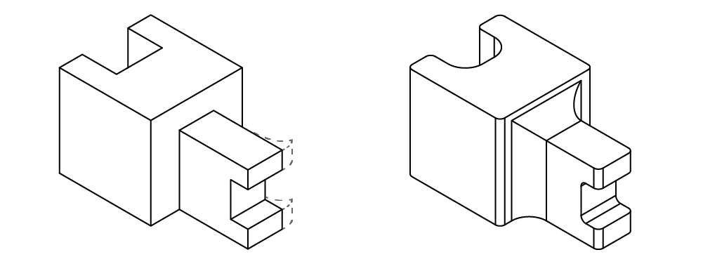
2. Maximize Bed Contact
Maximizing the contact your part has with the bed improves part success for multiple reasons, including print time, sintering performance, and supports necessary. Printing with the larges face of your part flat on the bed generally reduces the amount of support you need, thus cutting material usage and print time. Additionally, top-heavy parts are more likely to topple during sintering, so putting the larger features at the base of your print will also improve sintering performance.
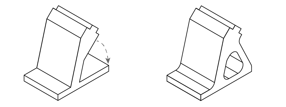
3. Reduce Supports
Fewer supports reduce printing and processing time on the printer. While supports are necessary to prevent overhang collapse during printing and sintering, reducing supports by adding features as simple as chamfers and fillets on edges can decrease the supports needed, overall cutting down on print time and material consumption. The supports are printed metal, just like the part, and enable uniform shrinkage between part and supports for a successful finished product. A release interface allows the supports and raft to separate from the part with a set of pliers or a mallet. While metal supports are easy to remove with hand tools, make sure that they are accessible and can be removed before you kick off the print. If not, consider modifying some of the overhangs to improve support removal.
4. Consider Batch Processing
The more parts you can pack into a sintering run or a wash, the lower cost you achieve per part. If you are producing parts in volume, it is important to consider how parts will be processed in batch. Consider how your parts will pack within the wash and furnace to save time and processing costs.
Optimizing Designs for the Washing Process
The time it takes for a part to wash depends upon the thickness of that part. As a part is washed, the fluid slowly dissolves some of the binder material away, opening up channels that allow it to flow deeper into the part and dissolve more binder. So the thicker your part is, the longer it will take to wash. A good way to imagine it is to determine the largest sphere that can fit within your part. By shelling out large volumes and increasing surface area, you can minimize the time your parts spend in the wash.
Optimizing Designs for the Sintering Process
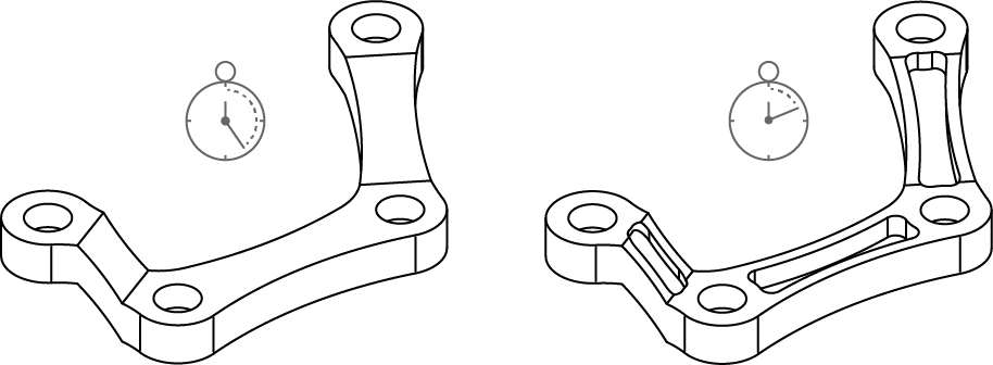
Reduce Stress Concentrations
Parts undergo thermal stresses in the furnace because they are pulling themselves together as they shrink. During the sintering cycle, most of the binder is removed, then the metal particles start to fuse and pull each other together, then the furnace cools so that the parts can be removed. Drastic changes in part thickness can cause parts to warp or curl due to thermal stresses, so you can reduce stress concentrations by filleting your edges, maintaining a consistent wall thickness, and designing in gradual changes in thickness.
Ensure Features are Well Balanced
As parts go through the sintering process, the heat induces a clay-like state that makes them malleable. If your parts don’t need supports, ensure they are inherently stable in their printed orientation. In this state you can think of your part behaving like clay or putty. Top-heavy, cantilevered, or tall and thin features may print well, but may collapse in the furnace if they are not inherently stable. Consider re-orienting your part to put heavier features of your part by it's base, or to add supports where they didn't generate previously.
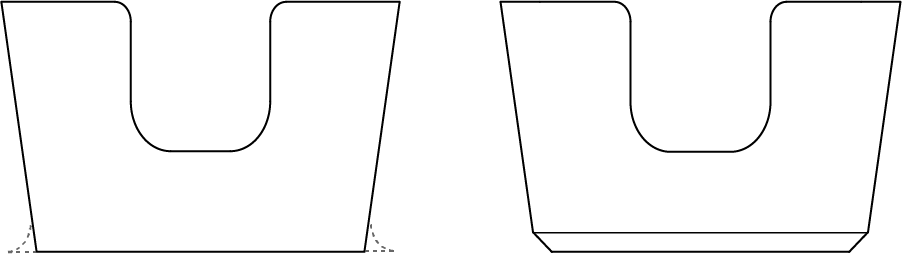
Chamfer Bottom Edges
The bottom edge of your part may splay out slightly during sintering. Adding a 0.5-1.0 mm (0.02”-0.04”) chamfer to the bottom edges of your part will prevent splayed edges, especially on small features. These chamfers also ensure smooth, well-aligned interfaces with hardware, especially in holes and channels on the bottom of your part.