
Efficient Fiber Routing Techniques Part 2: Advanced Routing Options
Editor’s Note: This is Part Two of a series on efficient fiber routing techniques using the Markforged 3D printer. If you are unfamiliar with the printer and are interested in learning more, please contact us here. To get up to speed with efficient fiber routing techniques, feel free to read Part One here!
Advanced Fiber Routing Techniques
Designing for 3D printing takes just as much work as designing for any other manufacturing process, and especially with our high-strength 3D printer, considering your manufacturing method is essential. There are some geometries and techniques that are very well suited for some processes and others not so much – we hope to encourage you to think about how you can use our unique fiber routing method efficiently and effectively to increase the strength of your 3D printed parts. Last week we covered some basic fiber routing techniques, including sandwich paneling, perimeter reinforcement, and shelling, describing what the different reinforcement options do and how to use them well. In this post, I’ll expand upon some of the concepts in last week’s post to show how to make your parts stronger with more advanced fiber routing techniques.
Optimizing for a Specific Direction of Strength
While concentric reinforcement will reinforce with fiber around the perimeter of the part, it is sometimes necessary to reinforce for a specific direction or loading scenario. In many cases, the parts you are printing require strength in certain areas based upon a known loading condition. You can efficiently improve the strength of your part by aligning fibers in that direction using our “fiber angles” option.
Traditional composites are composed of many layer of composite fibers, and in each layer the fibers are arranged in a particular direction, or “fiber angle”. To create a uniform sheet of composite fiber, each layer is rotated by a specific angle from the previous one until eventually the entire composite sheet is quasi-isotropic.

If you require strength in a particular direction, instead of constantly rotating the sheets of fiber, you can align them all in one or a few key directions. The fibers align with the loading condition of the part, thus optimizing the part for strength in that direction. The part below is a drone arm, primarily requiring reinforcement along the length of the arm to prevent it from bending. By default, the fiber angles will rotate when you reinforce with isotropic fill to simulate a quasi-isotropic weave.
In order to reinforce this part efficiently, you can edit the settings of an isotropic fill part (either in external or internal view) and set the fiber angles of every reinforced layer to 0. You can do this for a group of fibers or for a single layer. This maximizes the stiffness of the part along the length of the arm.

This technique can be expanded to multiple directions as well – if there are two primary directions that need reinforcement, you can set the fiber angles to rotate between the two directions to make the part strong in both directions.

Fiber Striping
Fiber striping entails multiple stacked sandwich panels to further reinforce the part in bending on the XY plane. If you have a thicker part with a fairly consistent cross section, you can use fiber striping to stiffen the part further with superimposed sandwich paneling to give it more consistent fiber reinforcement and much more torsional strength.

Selective Reinforcement
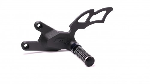
While fiber striping and shelling usually work best for parts with fairly consistent cross sections throughout, sometimes it makes more sense to reinforce specific sections or features of the part rather than reinforcing with evenly spaced stripes of fiber. In these cases, some considerations need to be taken into account to keep your sandwich panels even. We can break down the part below, a rear foot peg mount for a motorcycle from customer STS Turbo, into two sections: the top wing piece, preventing the rider’s foot from getting too close to the rear tire suspension, and the load-bearing mount section, with bolt holes to mount the foot peg and to mount to the rest of the bike.

The part needs to be stiff and resistant to flexing, but a standard sandwich panel will not reinforce the part in the way we need – adding fiber to the very top layers and very bottom layers will create an uneven sandwich panel and result in part failure. To get around this issue, we can create two even sections of sandwich panel – one sandwiching the “foot guard” section of the part, and one sandwiching the mounting bracket segment of the part. This is known as selective reinforcement – we are defining specific regions that require reinforcement, and ensuring that there are even sandwich panels bounding each region.

The part then needs to be further reinforced around the boltholes, to improve the part strength locally and to support the weight applied to the foot peg, which bolts to the foot peg spacer nub at the top of the part.
Combinations
The layer-level granularity of control that Eiger gives allows you to efficiently reinforce in more ways than one – all of these methods serve as guidelines for reinforcement and can be used together in many different ways. In last week’s post I described how shelling with isotropic and concentric fill can ensure a stronger part, and similar procedures can be implemented with these techniques.
The foot peg mount example I used above is an efficient fiber routing method for resisting in-plane bending with selective reinforcement, but may require more strength for a reliable and robust solution. The wing section of the piece isn’t load bearing but should resist in-plane bending, while the section with the mounting pattern will undergo compressive loads from the bolts holding it down and torsional loads because the foot peg will be supporting the weight of the rider. I’m going to add a section of layers beneath the counterbored hole to reinforce the bolt holes. This section of fiber is relatively centered within its region, so another layer to balance the sandwich isn’t necessary.

Next I’m going to shell the lower region of the part to improve its strength in bending about the Z axis to help resist the weight of the rider, as I described in our previous post. Lastly, I’m going to add concentric fiber reinforcement to the nub at the top of the part. This improves the compressive strength of the part once the foot peg is bolted on, and improves the torsional strength of the part, preventing the foot peg from torquing down and out of the hole.

Now the part is selectively reinforced using a few different fiber routing techniques covered in this series of posts. If you have any questions please let us know, and I hope we were able to help improve your fiber routing intuition!
If you don’t currently have a Markforged printer but want to see one in action, please feel free to request a demo and try out our Eiger software here.
All of the blogs and the information contained within those blogs are copyright by Markforged, Inc. and may not be copied, modified, or adopted in any way without our written permission. Our blogs may contain our service marks or trademarks, as well as of those our affiliates. Your use of our blogs does not constitute any right or license for you to use our service marks or trademarks without our prior permission. Markforged Information provided in our blogs should not be considered professional advice. We are under no obligation to update or revise blogs based on new information, subsequent events, or otherwise.
새로운 정보를 놓치지 마세요
Markforged의 최신 컨텐츠를 편지함으로 받으시려면 구독하십시오.