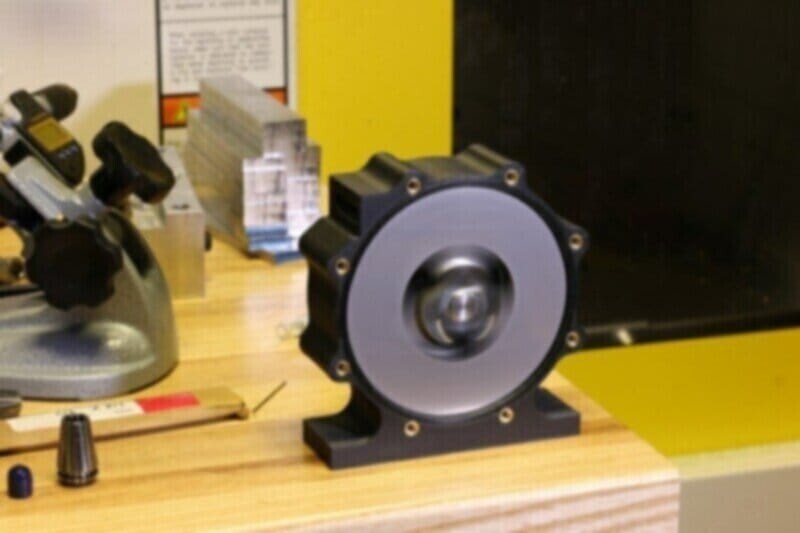
Designing a 3D Printed Tesla Turbine – Part 1
Introduction
Welcome to a two part mini-series on retrofitting a Tesla Turbine with Markforged parts. These blogs are application engineering in its purest form; we’ll be using techniques defined in previous instructional blog posts to design and print this part. By the end, we’ll hopefully have a functional Tesla Turbine with Markforged parts, capable of spinning at extremely high speeds. In the first installment, we’ll discuss Tesla Turbine basics and the Onyx reproduction of the turbine housing.
What is a Tesla Turbine?
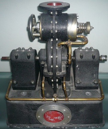
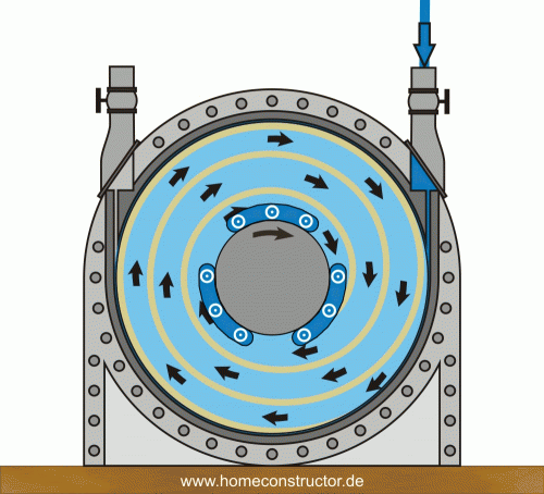
A Tesla Turbine is a blade-less centripetal flow turbine patented by Nikola Tesla in the early 20th century. Like its bladed turbine counterparts, it converts moving fluids into energy. However, instead of using angled blades to rotate a shaft, it uses smooth, parallel discs. Fluids enter the turbine traveling tangent to the discs on the outer edge of the turbine, forcing rotation by means of viscosity and surface layer adhesion. As the fluid slows and loses energy, it spirals toward the center of the turbine and exits through the exhaust port. The GIF below shows fluid motion and energy transfer in a Tesla Turbine.
When Nikola Tesla first created his Tesla Turbine, he described it as his “most important” invention. He theorized that the turbine could maintain 90% efficiency and that its simplicity in design and construction could lead to a revolution in power generation. He had a point: the two other rotary engines used at the time (piston engine and bladed turbine) were expensive to manufacture and had many parts that broke often. Unlike these two machines, the Tesla Turbine was extremely simple. There were no complex features to manufacture; in fact, the blades didn’t even have to be perfectly spaced. In theory, it was the perfect next step in rotary engines.
Unfortunately, in practice the machine had two key failure points. While Tesla first advertised the turbine as near perfectly efficient, in reality it only worked at about 40% efficiency. His understanding of boundary layer dynamics didn’t properly account for drag. This development was unfortunate, but not damning by any means; a turbine working at 40% efficiency still well out paces bladed turbines, which work in the 25-30% range. If they could reliably produce power at a rate superior to that of bladed turbines, Tesla turbines would be a household name. They couldn’t. Tesla Turbines spin at extremely high speed — Tesla’s original test turbines spun at speeds between 9,000 and 36,000 rpm — so fast that the blades on the turbines would warp severely during operation. Deformation hardly inspired confidence, and Tesla’s “most important” invention fell into obscurity. Today, Tesla turbines are produced at small scale as teaching props or demonstrations. While they never lived up to their billing, they’re still fascinating machines.
Reimagining a Turbine with 3D Printed Parts
For this project, we used a Tesla Turbine design from the Olin College Machine Shop that has three core systems: A shaft and rotor assembly, a bearing housing, and a turbine housing. The shaft assembly is fully constrained by the bearing housing and contained by the turbine housing. The bearing housing and turbine housing fit together with a close fit metal locating feature and eight screws.
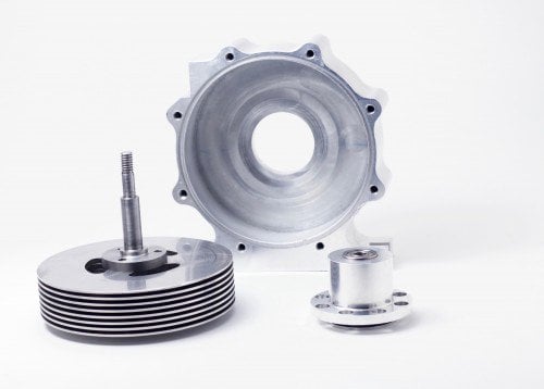
The simplicity of this turbine lends it well to machining. It has a wide variety of parts in both material and operation, from a hardened steel shaft to a polycarbonate housing cover. Every part on the turbine can be fabricated with a 2-Axis CNC machine or less. Below is a short BOM of machined parts in the turbine.
Turbine Housing: CNC Milled Aluminum
Bearing Holder: Turned and CNC Milled Aluminum
Shaft: Turned Steel
Shaft Spacers: Waterjet Steel
Blades: Waterjet then Turned Steel
Clamp Plate: CNC Milled Aluminum
Pulley: Turned Aluminum
Inlet Block: CNC Milled Aluminum
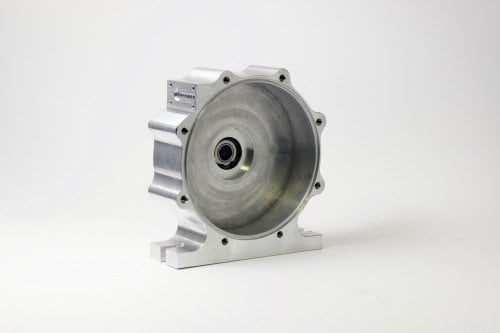
Some parts of the turbine don’t lend well to additive manufacturing. The precision and axial strength requirements make the steel shaft very difficult to print and the turbine blades and spacers benefit from being heavy (and thus having large rotational inertia). This is one rare application in which our impressive strength to weight ratio is not beneficial. For these reasons, we decided to leave the entire shaft assembly (shaft, spacers, blades, and clamp plate) alone and focus on the outer parts of the turbine. Instead, we focused on two parts: The turbine housing and the bearing housing (which we’ll discuss in the next installment). Unlike the shaft assembly, the housing was a perfect candidate for replacement. It’s fully aluminum, CNC milled, and lacking any tolerances smaller than .001”. By 3D printing it, we could maintain strength while drastically reducing weight.
Turbine Housing Requirements
The turbine housing had several important requirements. First, it needed to seamlessly mesh with the bearing housing. This meant that it needed to be +.001/-0 with respect to the locating feature on the bearing housing. Arguably the most important feature on the entire housing, a tight mesh mitigates vibrations that could rip the turbine apart at high speeds. Second, the turbine housing needed sixteen tapped holes; eight on the back plate to mount the bearing housing and eight more on the front to mount a cover plate. The polycarbonate cover plate is a minor part from a structural perspective, but is extremely important in insuring that the high pressure air flows through the turbine blades. Lastly, the cavity of the turbine must have a very small clearance fit with the blades. A small clearance fit gives clearance for the blades to turn while also minimizing the gap between the blades and the cavity wall, which causes significant efficiency loss.
Design and Fiber Routing
Redesigning the turbine for printing involved a few minor changes to satisfy the requirements above. First, we used unit tests to dimensionally verify the tolerancing required for the bearing housing mesh. To meet the required tolerance, we concluded that we need to undersize the hole in CAD by about .002” (Note: this is not a universal number, but instead one gleaned from the unit tests we ran. To learn more about unit tests, check out this blog post). Next, we replaced all the tapped holes in the aluminum version with cavities for heat-set tapped inserts (link here). Heat set inserts are a reliable method of fastening in 3D printed parts, ensuring sound connections where tapped holes cannot.
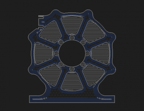
We routed concentric carbon fiber throughout the part to reinforce the design. To ensure that the bearing housing mount and subsequent forces would not deform the part, we filled the back wall of the part with as many fiber rings as we could. The walls of the part required less strength, so we settled with one ring of fiber on each wall layer. We were able to greatly the hoop strength of the part with minimal fiber with this strategy. Once the part was laid out in Eiger, we were ready to print.
Dimensional Verification
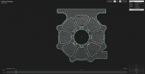
The turbine body fits on a Mark Two; however, we decided to print it on the Mark X for one simple reason: laser dimension verification. Unit tests told us that our dimensions should be accurate; now, we could verify accuracy mid-print. We configured two laser scans: one designed to check the mating feature with the bearing housing and another to check the cavity diameter. During the print, we checked each scan in Eiger to insure dimensional accuracy. The dimensioned scan showed an error of .0004″, well inside the tolerance.
Next Steps
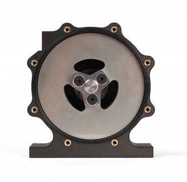
After the print finished, we inserted the threaded inserts and attached the aluminum bearing housing. Including the inserts, the printed turbine 170g, which was microscopic compared to the 570g aluminum housing. Once we verified that the metal housing and shaft assembly worked, we designed and printed the bearing housing, which we’ll cover in the next installment of this series.
Read the second part of this post here, and follow us on Facebook, Twitter, Instagram, and Linkedin for more updates!
All of the blogs and the information contained within those blogs are copyright by Markforged, Inc. and may not be copied, modified, or adopted in any way without our written permission. Our blogs may contain our service marks or trademarks, as well as of those our affiliates. Your use of our blogs does not constitute any right or license for you to use our service marks or trademarks without our prior permission. Markforged Information provided in our blogs should not be considered professional advice. We are under no obligation to update or revise blogs based on new information, subsequent events, or otherwise.
새로운 정보를 놓치지 마세요
Markforged의 최신 컨텐츠를 편지함으로 받으시려면 구독하십시오.