
MMF #1: 3D Printed Living Hinges with Bennett
Update: If you want to learn more about designing flexural elements and living hinges, watch the webinar recording about designing flexural elements and living hinges!
Original Post: MarkForged Mechanical Features [MMF] is a series of blog posts detailing best practices for designing common traditional engineering parts and mechanical features for composite reinforced 3D printing with MarkForged printers
Welcome to the first edition of Markforged Mechanical Features! We get questions from customers on a regular basis asking for help integrating the mechanical features they're accustomed to designing into 3D printed parts in order to take advantage of the functional strength of Markforged materials. To help spread this knowledge, we're going to regularly post articles on a specific engineering feature, and offer you tips and tricks on how to get the most out of your MarkForged printer.
Today, we're going to be talking about living hinges. At the most fundamental level, a living hinge is a thin, integral, mechanical feature of a part, generally made from plastic, which produces hinge-like functionality (rotation about a single axis) from the flexural deformation of the plastic. If that's a bit technical, you've probably seen living hinges in a variety of common consumer products - from the tops of floss containers to shampoo bottles. They're ubiquitous in injection molded packaging for consumer products, due to their excellent robustness and performance, with minimal post-processing or assembly steps - and with MarkForged, you can build them into your designs with industrial strength 3D printing.
Tech Terms - if you already are a pro with living hinges, feel free to skip this section
Let's get started with some basic terminology. Below is a labeled diagram of an example living hinge part that we'll discuss in a second.

Of note are the living hinge and the latch flexure. Both are flexible features which allow constrained rotation along a single axis. While they both are technically living hinges, they have two different functions and their varying geometries reflect this.
To help demonstrate 3D printed living hinges, I've enlisted the help of one of my fellow mechanical engineers here at Markforged. Bennett is a Senior Mechanical Engineer and previously spent three years designing electro-mechanical systems and injection molded casings at a major medical robotics company. He's one of our 3D modeling gurus, a regular Solidworks ninja, and has a deep-rooted interest in bringing hardcore mechanical design to the world of 3D printing. He's also been designing a bunch of living hinges at the office recently.
Bennett: I started printing living hinges because my brother (who is a mechanical engineer in the Bay Area) had asked me to print some sample parts he had designed on the Mark Two. He works in consumer electronics, where snaps and hinges are a major part of hardware design. Typically these types of parts get prototyped using a stereolithographic-based 3D printing process (SLA) which works well as an initial form and fit check. However, due to the brittleness of the materials used in SLA printing, you are effectively creating single use parts, as the hinge generally breaks after a single cycle. SLA allows you to visualize how a part will look in multiple configurations, but it does not allow for functional simulation of the end-use part. The alternative to an SLA prototype is to tool up and shoot a test injection mold. This is an expensive and, more importantly, long lead time process, not well-suited for rapid design iteration. My brother was curious to see if a MarkForged printer would be a better option, and sent me the STL files of some example parts to print. I got to work setting them up in Eiger and kicked off the prints on a Mark Two in house later that same day.
Working with living hinges on my brother's parts led me to begin experimenting with different design parameters for 3D printed living hinges on the Mark Two. The box below is a simple example I created that incorporates some of the design guidelines I developed while working with my brother's 3D model files.

Nick: One of the most important parts of printing living hinges is to get the part orientation correct in Eiger. Living hinges can generally be produced from either nylon (for a more flexible hinge) or kevlar-reinforced nylon (for a stiffer, but higher load-bearing hinge), but in either case, they need to be printed with the normal axis of the side profile of the hinge pointed in the direction of the Z axis. Another way to describe this orientation is the full side profile of the hinge, as displayed below, must lie in the horizontal XY plane.

The reason for this is two-fold and greatly affects hinge strength: first, fiber can only be laid in the XY plane, so to lay kevlar along the length of the hinge it must be oriented as such. Second, nylon tensile strength as-printed in a layer is much greater than the interlayer adhesion strength of the nylon. Both of these realities lead to the need for printing a living hinge in the orientation shown in the following screenshot from Eiger.

A common challenge that our new users often face when beginning to design for 3D printing is developing an understanding of the anisotropy of 3D printed parts.
Tech Terms
Anisotropic material - a material with directionally dependent material properties, often mechanical, along various axes of a section of the material - many woods, for example, split easily along their grain lines, but are difficult to break or cut across the grain, which is a great example of anisotropy. The opposite is an isotropic material, such as many metals, which have much more uniform properties regardless of orientation./Tech Terms
Bennett: Like Nick mentioned above, with FFF technology you're going to get your greatest strength in the XY plane, so you should take advantage of that. Additionally, one of my favorite things about designing in nylon is how fatigue resistant it can be. When you combine these two factors it follows that the optimal orientation for a living hinge will have the hinge cross section in the horizontal XY plane. As you thicken the hinge, you bump up its stiffness. In this part, there is a lid hinge that needs a full 180 degrees of motion, and a latch hinge that has a much smaller requirement on angular movement, but should hold the lid closed when snapped shut. Based on those requirements I made the lid hinge as thin as possible, while increasing the thickness of the latch hinge for stiffness and to promote the box staying latched until intentionally opened by a user. I modeled the lid in its neutral position (90 degrees open) and the latch hinge slightly closed to help it snap into place. 3D printed flexible parts, much like their injection molded counterparts, have a tendency to return to their as-printed state unless they undergo significant plastic deformation, so you should keep this in mind when designing the desired neutral position of your parts.

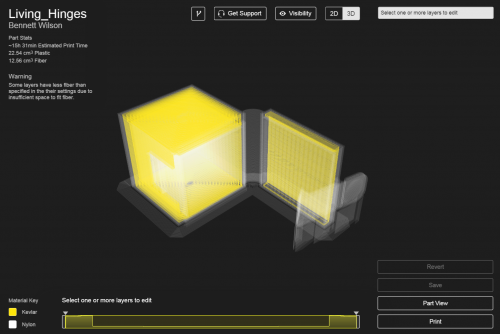
Next was to move things into Eiger. I rotated the part to ensure my hinges printed in the desired orientation, and turned on fiber. I used a concentric fill designed to totally fill the part with fiber, and applied the settings to the entire part. Eiger gave me a warning about not having sufficient space to fit fiber, but this was expected as I designed the hinges themselves to be smaller than the minimum required thickness for fiber reinforcement. With the Mark Two I was, however, able to fit fiber throughout the base of the part, as well as the lid without issue - something that I would have never been able to do with the Mark One due to the small size of this part. I turned on the brim setting for this part as well to make sure my tall thin sections would be fully supported during their early layers.
Technical Details
- Lid hinge thickness: 0.7 mm, for maximum flexibility
- Latch hinge thickness: 1.2 mm, for greater stiffness to prevent unintentional opening
- Parts modeled in open and closed positions to confirm the bend radius was appropriate, before final print configuration was chosen
Want to print your own? Bennett's Solidworks files: Living_Hinges CAD SW file
Eiger-ready: Living_Hinges STL
All of the blogs and the information contained within those blogs are copyright by Markforged, Inc. and may not be copied, modified, or adopted in any way without our written permission. Our blogs may contain our service marks or trademarks, as well as of those our affiliates. Your use of our blogs does not constitute any right or license for you to use our service marks or trademarks without our prior permission. Markforged Information provided in our blogs should not be considered professional advice. We are under no obligation to update or revise blogs based on new information, subsequent events, or otherwise.
Never miss an article
Subscribe to get new Markforged content in your inbox