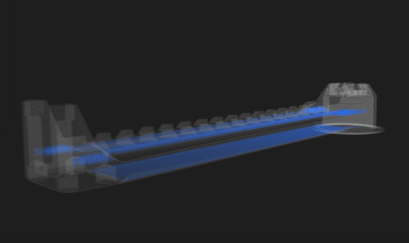
High Strength 3D Printing – Isotropic Fill Part 2
Update: If you are interested in learning more about how different fills can strengthen your part in various ways and the science behind it, join us on June 21 at 11am EDT for a webinar (Register here)!
Writer’s Note: This is the second post of our two part series on designing the strongest possible parts with Eiger’s Isotropic Fiber fill type, using carbon fiber on the Mark Two. Our previous post detailed the background on why we print reinforcement in our specific Isotropic pattern — this post will cover how to best apply that fill type to produce the strongest parts with the most efficient use of our carbon fiber 3D printing technology.
Not all fibers are equal – put your fiber where your forces are!
We previously covered the fundamentals of composite reinforcement, as well as how to apply different fiber orientations in Eiger. Now it’s time to discuss reinforcement efficiency – 3D printing the strongest parts without unnecessary weight or cost. Reinforcing a layer with Eiger’s Isotropic Fiber fill will add strength and stiffness to that layer — but do you actually need that strength there? We’re going to show you that the location of a layer in relation to the loads applied to the overall part is probably the most important consideration when designing for efficient use of reinforcement in high strength 3D printing.
Before we dive into actually reinforcing anything, it’s important to understand how physical parts respond when a force or load is applied to their external geometries. As an example, let’s look at a simply supported beam — a beam that is supported from below at both ends with one end free to translate along the x axis, as in the image below.
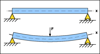
As you apply a force F to the beam, the beam will begin to bend or deflect downwards, by an amount which depends on both the magnitude of F and the geometry and material properties of the beam. If you were to look at the internal stresses generated by the force F in a representative side profile section of the beam as it experiences bending, you would find that the side of the beam closest to the downwards pointing load experiences compression, while the side of the beam furthest away experiences an equal force but in tension.
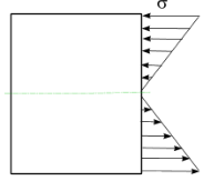
The diagram above details the internal bending stresses σ across the thickness of the beam, where a longer arrow indicates the larger the bending stress. It’s immediately clear that the highest bending stresses are developed at the top and bottom surfaces of the beam while in bending, with the centerline of the beam, called the neutral axis, experiencing zero force. The opposite directions of the arrows on either side of the neutral axis indicate the direction of force — compression or tension — that the region of the beam experiences. Overall this means that if you’re optimizing for your use of high strength material in a part that experiences bending, you should prioritize placing that material where the highest forces occur – near the surface of the beam. This simple fact is the reason behind the design of I-beams and sandwich panel construction.
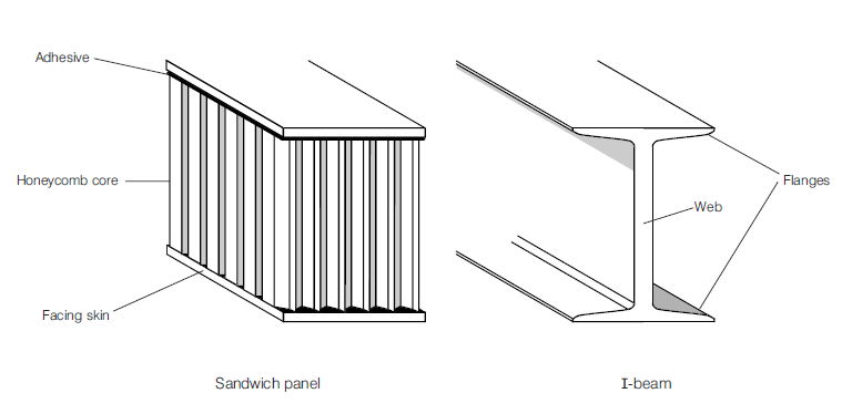
The development of both I-beams and sandwich panels resulted from the desire to produce a high-strength, high-stiffness plate or beam with a minimum of weight. As we’ve seen, the highest forces in bending occur at the outer surfaces of a beam, so adding high strength material at those surfaces will do the most to resist bending forces. Near the center of the beam, however, high strength materials don’t contribute nearly as much to the overall beam strength, since they are exposed to much lower forces. These materials still add the same amount of weight, however so the overall strength per weight efficiency of regions near the neutral axis is greatly diminished. The I-beam geometry was developed in order to provide a high strength-to-weight single-material metal beam. The advent of advanced materials enabled the development of multi-material sandwich panel construction, which distributes the forces normally absorbed by the I-beam web (the vertical portion of the I-beam) over a much larger area, as well as allowing much lighter core materials to be used since the forces involved don’t need to be concentrated over a single web.
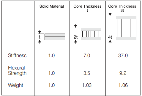
Superposition of sandwich panels
With all that theory out of the way, let’s dive into reinforcing parts in Eiger. By default, Eiger will attempt to generate a sandwich panel when you add fiber in the external ‘Part View’ page that you first encounter when opening a part from your Eiger library.
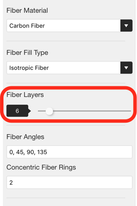
Half of the ‘Fiber Layers’ value that you’ve chosen to add to a part are automatically added to the bottom layers of the part above the first four (by default) layers configured as solid plastic Floor layers, and the other half of the Fiber Layers are added to the top of the part, below the top four (again by default) layers configured as solid plastic layers. This algorithm works great if the part you’re trying to reinforce is symmetrical about a plane parallel to the printbed, such as the landing gear for the Snotbot drone that a team at Olin College printed.
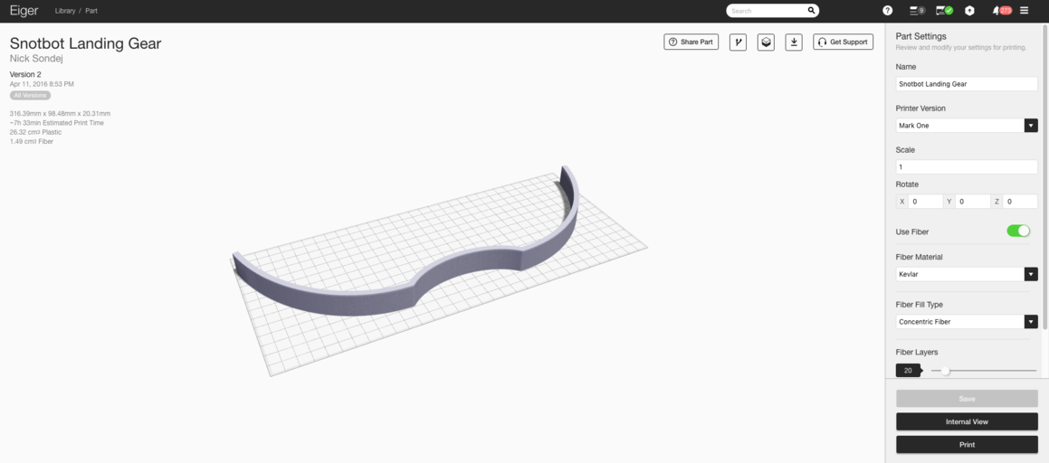
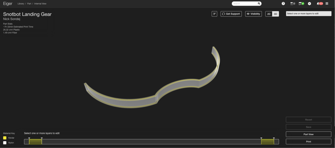
As you can see in the photos above, the algorithm added 10 layers of Kevlar reinforcement to the top and bottom of the part. Since the part is symmetrical about an XY plane, the default fiber layer algorithm resulted in the desired behavior, sandwich panel reinforcement.
But what happens when your part doesn’t meet the symmetry condition outlined above? In that case, the default algorithm won’t provide the reinforcement you’re looking for, as in the case of the motorcycle brake lever part we often use as a strength demonstrator at trade shows.
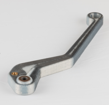
As you can see in the below screenshot, the default fiber algorithm adds fiber to the bottom of the part, but does not add fiber where it is needed to the top of the part to complete the sandwich panel because the small raised ridge where the bronze bushing is pressed causes the part to be asymmetric. We actually want fiber further away from the top layer of the part than from the bottom of the part in order to produce the largest sandwich panel possible.
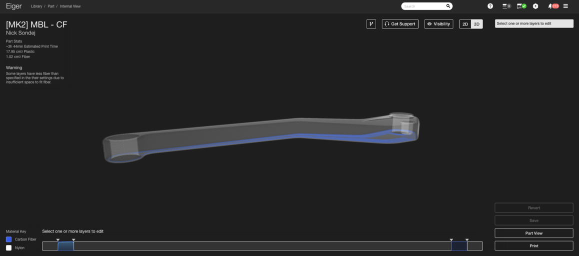
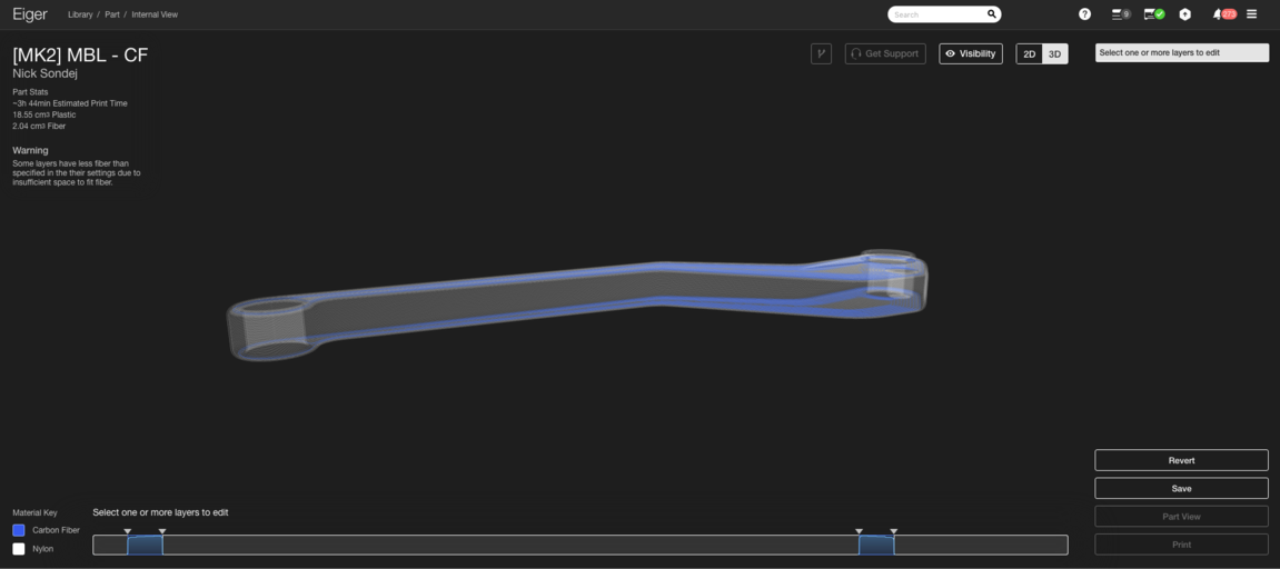
This brings us to the first general guideline for reinforcing the strongest parts on your Markforged printer – try to create the largest sandwich panels you can first in a part, by using Isotropic Fiber fill with one or two concentric rings in layers with the most distance separating them.
Guideline #1: Create the largest, thickest sandwich panel first, using Isotropic Fiber fill
In the case of the motorcycle brake lever above, this means that you should move the top layer group down until you have fiber running at the top of the lever body as seen in the following image.
What happens when you have multiple, potentially overlapping regions ripe for sandwich panel construction, as in this crank arm from the UW-Madison Human Powered Vehicles Team‘s 2016 design?
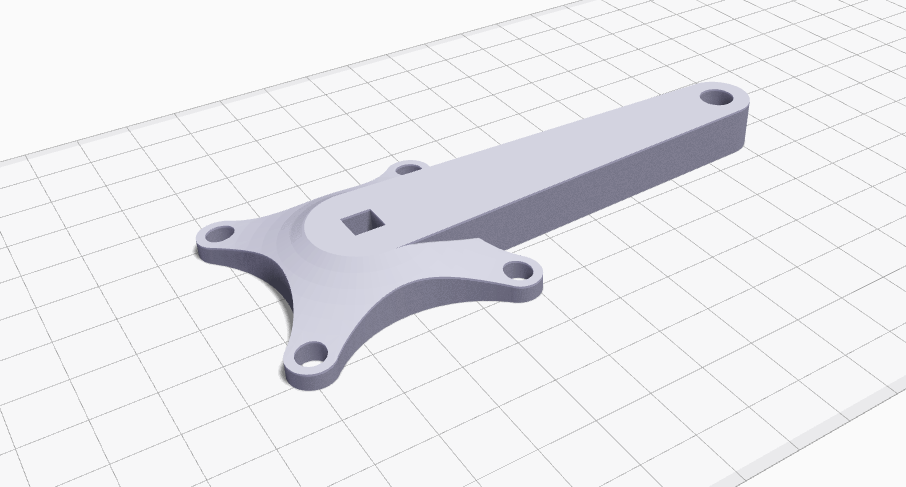
There are clearly multiple regions which could become sandwich panels – there’s the top and bottom of the arm itself (the longer portion of the structure), as well as the top and bottom sections of the four pointed flange which would benefit from composite reinforcement as well. Since bolts will be run through all four holes, the addition of fiber would better resist the stress cones produced by the bolts. While you might be able to run a thorough (and lengthy) loading simulation to find the best places to add fiber, it’s easiest (and probably most efficient) to just start building sandwich panels. First, we let the default fiber algorithm add four layers of Isotropic Fiber fill to the top and bottom of the part.
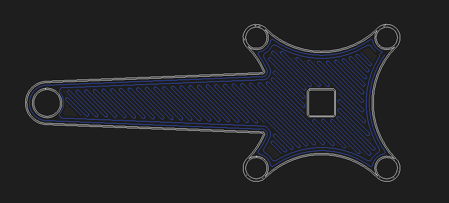
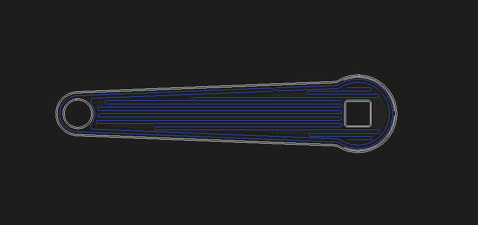
These two layers have very different cross-sectional areas which isn’t altogether ideal (it’s best to attempt to have sandwich panel ‘skin’ layers of roughly equal cross-sectional area if geometry allows), but reinforcing the largest possible sandwich panel in the part means that this crank arm will be more able to resist the large bending loads of a cyclist’s leg.
We also need to reinforce the flange with the four holes that connects this crank arm to the actual crank. Focusing on just the flange, we’ve already reinforced the bottom of it when we reinforced the overall part in the first step, we just need to reinforce a group of layers about 25 layers into the part, where the flange ends. But if we add a layer group there, we have three separate fiber layers. We’ve only talked about sandwich panels with two composite skins, one on either side — have we ruined one of the sandwich panels?
Guideline #2: You can add and superimpose sandwich panels in order to fully reinforce a part
This brings us to our second guideline – our concept of ‘sandwich panels’ isn’t only additive, and we can superimpose one sandwich panel over a larger or smaller one, reusing the composite ‘skin’ layer from the previous sandwich.
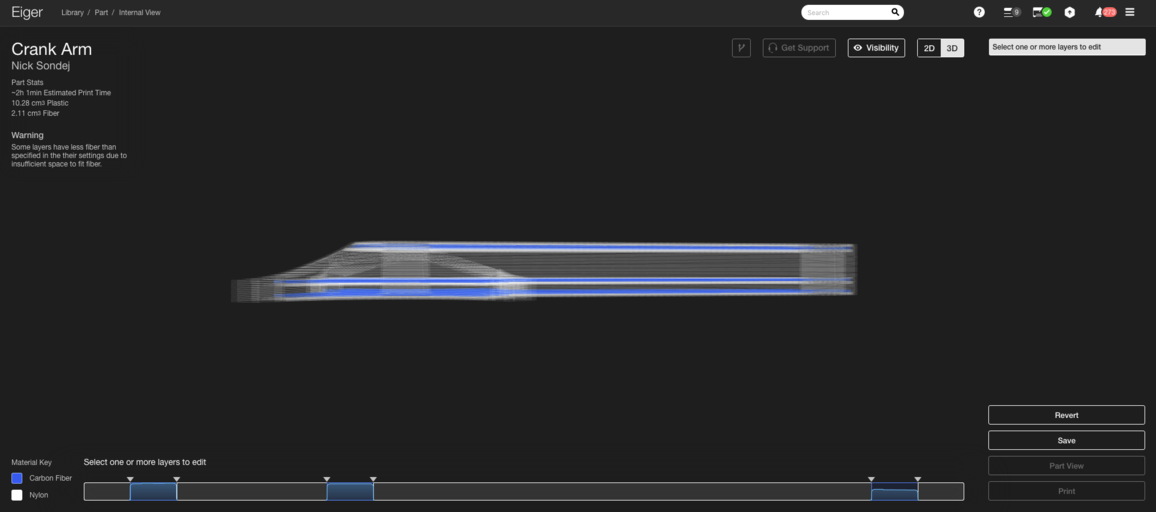
Thus, this results in the configuration in the image above, with a thinner sandwich panel reinforcing the crank arm flange, and a thicker sandwich panel reinforcing the overall part. Both sandwich panel embodiments use the carbon reinforcement layer group at the bottom of the part as their lower skin layer.
At this point, the part is already extremely strong, but since bicycle crank arms are subjected to quite a bit of complicated torsional loading patterns, we’re going to add one more fiber layer. This is because shear stresses can be caused by certain applied torsional loads. Unlike bending stresses, shear stresses have a maximum magnitude at the neutral axis or midplane of a part, and since it’s hard to predict whether the crank arm will be exposed these loading conditions, its easiest to just add one more composite layer group around the midplane of the crank arm.
Guideline #3: Adding a group of Isotropic fiber layers in the mid-plane can better resist certain torsional loading patterns
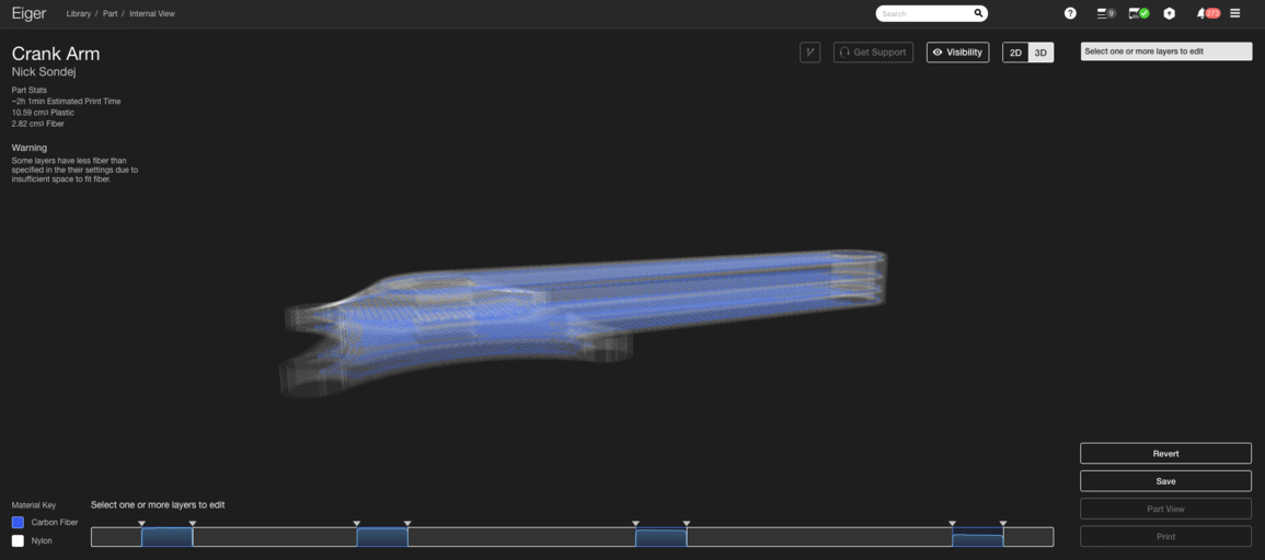
This results in the final configuration seen in the above image – with four separate groups of fiber creating a series of sandwich panels. This is one of the strongest configurations we can produce, while still preserving an overall lightweight part.
To summarize, our three guidelines for high strength 3D printing using fiber reinforcement are:
1. Create the largest, thickest sandwich panel first, using Isotropic Fiber fill
2. You can add and superimpose sandwich panels in order to fully reinforce a part
3. Adding a group of Isotropic fiber layers in the midplane can better resist certain torsional loading patterns
These guidelines aren’t foolproof and there are always going to be exceptions, but they’re a great place to start when designing your strongest parts.
Want to reinforce a part yourself? Learn more about the Mark Two today!
All of the blogs and the information contained within those blogs are copyright by Markforged, Inc. and may not be copied, modified, or adopted in any way without our written permission. Our blogs may contain our service marks or trademarks, as well as of those our affiliates. Your use of our blogs does not constitute any right or license for you to use our service marks or trademarks without our prior permission. Markforged Information provided in our blogs should not be considered professional advice. We are under no obligation to update or revise blogs based on new information, subsequent events, or otherwise.
Never miss an article
Subscribe to get new Markforged content in your inbox