
Designing for Printing Part 2: Why 3D Printed Parts Warp and How to Stop It
Designing for 3D Printing (DF3DP) is a blog series devoted to 3D printing tips and tricks to follow when using any 3D printer that will guide you through reducing costs, print time, and material while also showing you how to get your parts the way you want them first try.
If you’ve ever used an FFF 3D printer, you’ve probably experienced part warping for large, long, or oddly shaped parts. Usually this means you either have to do some post processing to make them flat again, or you’ll have to just accept dealing with an uneven bottom surface that you probably assumed would print flat.
3D printed part warping is a tricky problem to get around; just because a 3D printer is reliable, doesn’t mean it won’t have this problem. 3D printed parts warp because of thermal deformation. When plastics heat up, they expand. When they cool, they shrink. Because FFF 3D printing almost always involves thermoplastics, this happens with almost every FFF 3D printer. On the printer side, there are two things that fix warping: a heated build plate, or a heated enclosure. These two solutions keep the part at temperature, so it doesn’t cool, therefore, no warping. Simple! Other 3D printers will have an enclosure that keeps the heat in, and/or an adhesive to apply to the build plate (like ours) which usually ends up helping reduce warping as well. Additionally, letting the part cool to room temperature before removing it will reduce warping because the part cools while still adhered to the build plate.
But really, it’s less about the system and more about the part design. The notion that “3D printers can print anything” is untrue (more on this in a future blog post!), because 3D printers often have as many limitations and design guidelines as other manufacturing methods. To name an example, the smallest feature size an FFF 3D printer can create is dependent upon nozzle diameter and gantry accuracy. Anyways, many parts warp simply because of the material limitations of FFF 3D printers combined with part design not optimized for 3D printing.
I’ve designed a simple triangular prism truncated on one edge that is fairly prone to warping (for reasons you’ll find out about soon). Here’s the 3D model in Eiger:

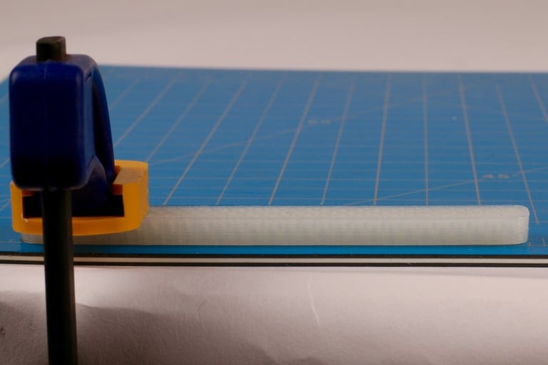
And here’s a shot of the part warping after it came off the build plate. To demonstrate warping, I’ve clamped down the piece on one side of the table and observed the deflection on the other side:

These five tips serve as 3D printing design guidelines so that you can reduce warping on 3D printed parts during your design process. I hope they help!
1. Fillet Edges and Design with Round, Natural Shapes in Mind.
When 3D printed parts warp, it’s because of a thermal moment formed around the edge of a part. This thermal moment is caused because when FFF printers lay down filament, they are heating the plastic until it is semi-fluidic and then cooling it down after it is extruded. When most materials cool, they want to shrink. In the case of FFF 3D printers, this means that each “line” of material will want to contract lengthwise. Usually, this is not enough to break adhesion with the build plate, but this force builds up as more layers are added, making the part warp. This is especially common with long, thin parts, like the test piece I’m using in this post, because of the lengthwise contraction.
When more corners are added to a line segment that wants to shrink, the corners will peel up because of the build up of stress at that location, as shown in the diagram below:

Sharp corners create stress concentrations, so corners are the most common geometries that induce warping. Adding a fillet to these corners reduces the stress concentrations because the sharp corner gets rounded off, and the stress gets distributed. In general, creating cross sections that are more round in shape when contacting the build plate will reduce warping – when engineers design parts they usually end up being rectangular in shape; that is commonly what is easiest to machine. But designing from the start with more round, natural shapes and surfaces will reduce warping because it distributes the stress build up. Below, I have edited the test piece by adding a fillet to the corners.

Even with this simple change, fillets on the edges reduced warping significantly.
Another quick tip with fillets – adding a fillet to the bottom edge of your part will allow you to remove it from the build plate more easily – it gives a good lip to get a scraper under!
2. Print parts with the largest face on the bottom.
As layers stack on top of one another, these forces multiply. If the layer above the one that was just placed down is slightly larger, then there is more added material that wants to shrink, so the force increases even further. This means the worst shapes to 3D print are shapes with larger cross sections as you go up, and shapes with sharp corners after long, straight segments, just like our warp test!
Parts don’t always warp just on their bottom layer, though – warping can occur wherever these geometry conditions exist. Frequently long, extruded overhangs end up curling up for the same reasons, even if they are supported, as shown by this thin angled overhang below:

So when 3D printing parts, it’s important to try and get the largest face on the bottom because parts tend to warp as the cross section gets larger on top of stacked layers. Additionally, the more surface area you have contacting the build plate, the better, because a larger surface area will hold better. I printed the truncated prism upside-down, in the orientation shown below:

And as you may expect, no warping:

Although this is a simple example, and with a part like this it may be clear that it should be printed with the largest face down, in some scenarios it is not quite as obvious, so remember to consider build orientation when designing the part.
3. Add a Brim
A brim can be added to parts using the “brim” tool, which essentially adds some extra contact area to the build plate surrounding your part.

This reduces warping or curling for two reasons. One, the part has an “extended” bottom surface, meaning that the contact with the build plate is larger than it would be normally. Two, any warping that occurs transfers to the brim, which will take the worst of it. The brim additionally gives a better surface for support structures to adhere to. Our support structures are long, thin lines, which, as I explained above, really want to contract. If you have a lot of support material beneath your part, a brim will provide a good surface for the support structures to stick to. The supports won’t curl as much because they are sticking to the brim – a flat, large area surface sticking to the build plate. Below is a test of the part with a brim:

4. Make Your Own Brim
Sometimes, due to odd build plate contact point geometries, parts will still warp just because the brim may not be large enough or curved enough. In these unique cases, it may be necessary to CAD your own brim. What is suggested in these scenarios is to add thin, round “dots” to all of the corners of your part, which will provide more surface area contact with the build plate at key points where warping occurs.

My own designed brims eliminate warping just as well as our pre-fab brim, and may come in handy for more complicated parts:

5. Add Composite Fiber to Your Part
One of the unique capabilities of the Mark Two is its ability to lay fiber inside components to make stiffer and stronger 3D printed parts. Because of the composite material capabilities of Markforged 3D printers, to reduce warping in a part you can add fiber to the bottom few layers to increase its stiffness.

This essentially forces the bottom layers to be flat, making it almost impossible for them to warp. If you’re doing this, however, remember to balance the composite by creating a sandwich of fiber at a top and bottom surface of your part to optimize for torsional strength, as described in this blog post. As you can see, With no design alterations to the original part, the test warp piece remains flat:

Extra Tip: Print in Onyx!
As described in tip #5, minimizing warping can be tackled from a materials standpoint with our Continuous Fiber Fabrication (CFF) method. But some of our other materials come in handy when solving this problem as well. Onyx, our micro-carbon reinforced filament, does not deform nearly as much under heat. This means that it warps much less than our standard nylon, and creates much more dimensionally stable parts. You can read more about the dimensional stability of Onyx here. With no fiber reinforcement, the Onyx filament remains stable:

I hope this post helped you understand why 3D printed parts warp and how to improve your designs to eliminate warping! If you want to try out your own experiments for reducing warping on 3D printed parts, give it a shot with the stl file and mfp file yourself! If you have any questions, suggestions, or ideas for future blog posts please let us know at printstronger@markforged.com.
All of the blogs and the information contained within those blogs are copyright by Markforged, Inc. and may not be copied, modified, or adopted in any way without our written permission. Our blogs may contain our service marks or trademarks, as well as of those our affiliates. Your use of our blogs does not constitute any right or license for you to use our service marks or trademarks without our prior permission. Markforged Information provided in our blogs should not be considered professional advice. We are under no obligation to update or revise blogs based on new information, subsequent events, or otherwise.
Never miss an article
Subscribe to get new Markforged content in your inbox